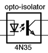

They also help you ensure that your system is up to code. They are used to build circuits and manufacture electronic devices. Wiring schematics are diagrams that show the connections between various parts of an electrical system. Some electrical and electronics symbols also represent other electronics, such as circuit breakers and fuses, which help protect people from electrical shock. You may also see symbols such as push buttons and indicator lights. electrical and electronics symbols help represent different components, such as light bulbs, motors, and switches. When reading an electrical schematic diagram, it can be helpful to know what all the different symbols mean. Common electrical and electronics symbols And since transistors can have positive or negative doping, they also have their symbols. Other devices have special symbols for their properties, such as Schottky diode and zener diode. Likewise, light-emitting diodes (LEDs) have lines pointing away from the diode, whereas photodiodes produce electric energy from light, and their arrows point toward the diode. For example, we enhance the standard diode symbol with lines pointing away. In a schematic diagram, different symbols represent different components. For example, an electrical outlet produces electricity, whereas a switch turns electrical energy into heat, motion, or sound. In addition to referring to components, symbols denote the functions of devices. In electrical and electronics engineering, electrical and electronic symbols help describe electrical and electronic components. Request PCB Manufacturing & Assembly Quote Now Electronic Circuit Symbols – Importance & Reference Designators Some symbols are also assigned special notes or asterisks to indicate their value. This standard lists the symbols that are helpful in circuit diagrams. Some symbols are part of the ARI Standard 130-88. In addition, knowing the meaning behind them will save you time and effort. As a result, most electronics engineers know these standards.Ī basic understanding of electrical symbols will help you troubleshoot electrical circuits. While there are many differences, both systems are widely used and are generally equivalent. The most common ones are the IEC 60617 and ANSI/IEEE standards. However, most systems are common and widely used. These basic symbols will allow anyone to create an electrical diagram.ĭifferent countries use different systems for electrical and electronics symbols. For example, a battery can have a capacitor and a resistor. You can also use these symbols to represent more complex circuits. Knowing these can help you create a more accurate and understandable electrical diagram.

When we use a transformer, it will help reduce tension in the circuit, so the electricity flowing through the circuit is more evenly distributed.īasic electrical and electronics symbols include the earth electrode, battery, and resistor. The magnetic field keeps an AC circuit’s frequency steady and reduces circuit tension. It works by coupling two or more coils by magnetic induction to create a magnetic field. There are many different uses for electrical and electronics symbols.Ī transformer is a device that helps maintain the frequency of an AC circuit. If you’re looking for a specific device or function, you can search for its corresponding symbol. These symbols are helpful in schematic diagrams of electrical and electronics circuits. For example, it can represent wires, resistors, transistors, and batteries. An electrical and electronics symbol is a pictogram that represents an electrical device or function.


 0 kommentar(er)
